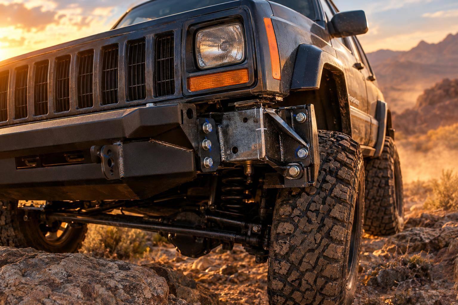
XJ bumper tie-ins spread loads across the unibody, but they don’t make a bumper recovery-rated or crash-safe. I start by checking the kit’s model-year fit and the rails for damage – before drilling or welding.
My installation checklist covers 3 stages:
- Plan the fit: Measure mounting holes, plate positions, and space for hardware, steering parts, and the winch.
- Attach the assembly: Test-fit with bolts loose, use specified backing plates and hardware, and weld only where the design calls for it. Protect bare steel and torque bolts to the specified values.
- Check the result: Fix gaps or misalignment without forcing parts together. Check bumper clearance through steering and suspension travel, and confirm recovery points connect to the reinforced mounting structure.
<u>I stop if the rails are damaged or the parts won’t fit as specified.</u> Repairs or manufacturer guidance come before final tightening – not improvised spacers, bolts, or holes.
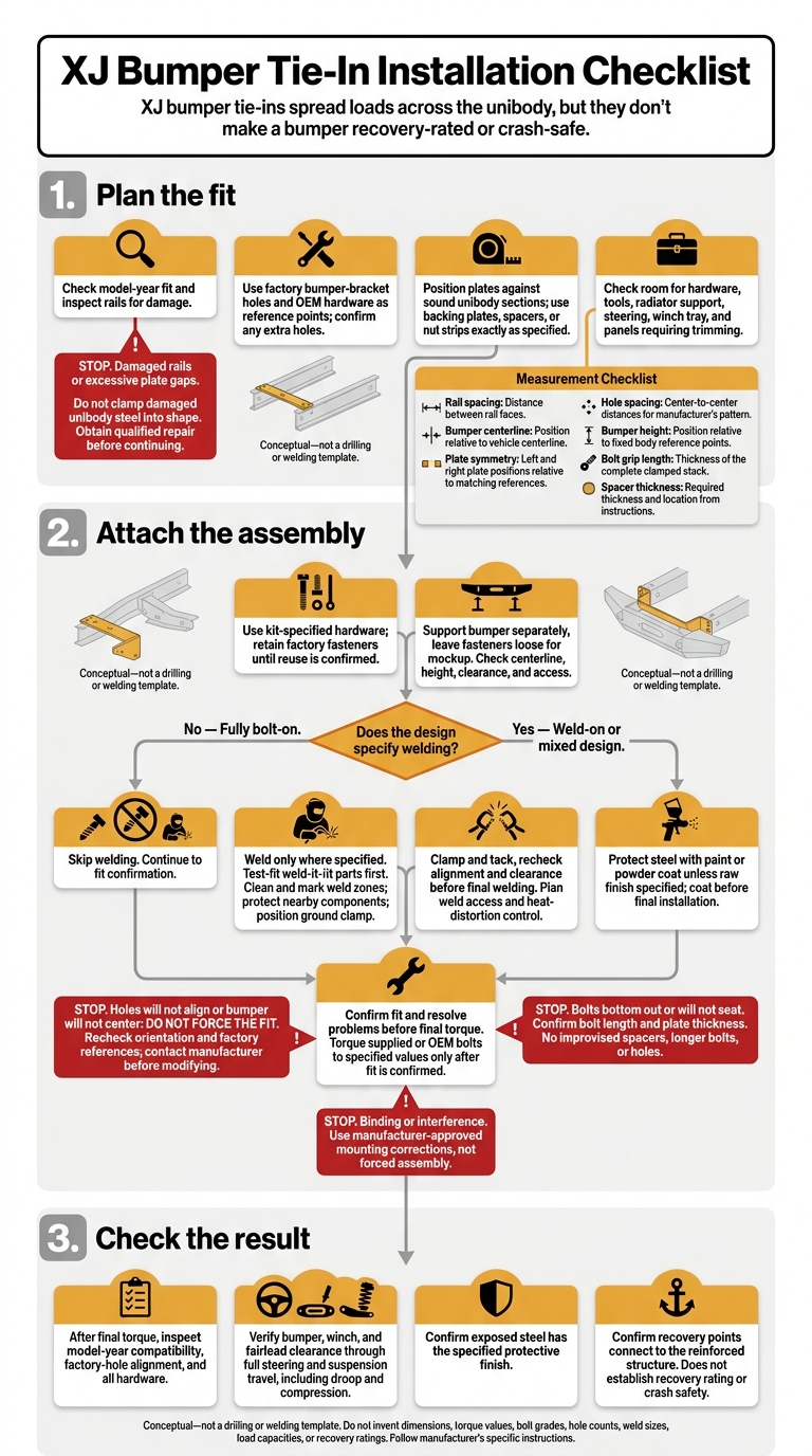
XJ Bumper Tie-In Installation Checklist
Map Mounting Points and Plan Plate Layout
With the mounting points marked, check the plate layout against the factory holes and nearby structure before drilling.
Measure Mounting Holes and Clearances
Use the factory bumper-bracket holes and OEM hardware locations as reference points for the kit’s side and lower attachments. Check whether your model year requires extra holes or hardware.
During mockup, leave room for bolts, backing plates, and any specified nut strips. Check clearance around the radiator support, steering components, winch tray or fairlead opening, and panels that need trimming.
| Measurement | What to record |
|---|---|
| Rail spacing | Distance between rail faces where the plates will sit |
| Bumper centerline | Position relative to the vehicle centerline; check against the grille or radiator support |
| Plate symmetry | Left and right plate positions relative to matching reference points |
| Hole spacing | Center-to-center distances for each attachment in the manufacturer’s pattern |
| Bumper height | Position relative to fixed body reference points on both sides |
| Bolt grip length | Thickness of the complete clamped stack at each joint |
| Spacer thickness | Required thickness and location from the kit instructions |
Position Plates and Support the Bolted Load Path
Once you’ve confirmed the hole pattern, position the plates so sound sections of the unibody rails carry the bumper load – not trim or unsupported thin sheet metal.
Fit the plates against the rails. Install backing plates, spacers, or nut strips exactly as specified to support the bolted load path and keep the mockup aligned.
Compare Bolt-On and Weld-On Designs
Before committing to the layout, confirm the attachment points and specified weld locations for the full assembly.
| Design | Fit and attachment planning | Weld planning |
|---|---|---|
| Bolt-on plates | Align the specified mounting holes and leave room for hardware and backing plates | No welding for a fully bolt-on design |
| Weld-on reinforcement | Fit plates to the rail at the specified attachment locations | Check weld access and plan how to control heat distortion |
| Mixed bolt-on/weld-on design | Align bolted joints while positioning welded reinforcement | Plan weld locations and heat control around the bolted interfaces |
Use this layout to select hardware and plan any weld locations in the next step.
sbb-itb-afc4690
Test-Fit and Attach the Assembly
Choose Hardware and Assemble Loosely
Use the hardware specified by the kit, and keep the factory fasteners until you confirm whether they’ll be reused. Support the bumper separately and leave all fasteners loose while you check its position on the plates, clearance, and tool access. Trim any factory plastic or fiberglass needed for clearance before final tightening.
For a fully bolt-on assembly, skip the welding steps below. Otherwise, move to welding once the bumper sits correctly and all hardware clears.
Prepare Weld Locations and Tack Plates
Weld only where specified. Test-fit weld-it-yourself parts on the vehicle first – the vehicle serves as the jig. Clean and mark the weld zones, protect nearby wiring and fuel or brake lines, and position the ground clamp according to the welding setup.
Clamp and tack the plates in place. Then recheck the bumper’s centerline, height, and clearance before making the final welds. Once the tack fit holds the correct alignment and clearance, complete the welds and finish the steel.
Finish Welds, Protect Steel, and Torque Bolts
After welding, apply paint or powder coat to the steel unless a raw finish is specified. Coat weld-it-yourself parts before final installation. Once you’ve confirmed the fit, torque the supplied or OEM bolts to the specified values.
If the bumper still shifts, binds, or sits off-center, move to the fit-fix steps below.
Fix Common Installation Fit Problems
If the assembly shifts, binds, or sits off-center, run through these checks before tightening fasteners to final torque.
Align Mounting Holes and Center the Bumper
Loosen the assembly and check the plate orientation against the factory mounting points. If the bumper sits off-center, inspect the rails and compare the hole pattern with the mocked-up plate position.
Do not force the fit. If the holes still won’t line up or the bumper won’t center, contact the manufacturer before modifying any parts.
Resolve Plate Gaps and Clean Weld Zones
If alignment is correct but a plate won’t sit flush, check the rail for bends, cracks, or weakened metal. Don’t use clamps to pull damaged unibody steel into shape.
Stop if the gap is excessive or the structure is damaged. Have a qualified professional repair the rail before continuing. Then remove mill scale, rust, and contamination from the weld zones.
Check Winch Clearance and Bolt Length
Once the plates sit correctly, compare the winch and fairlead dimensions with the available mounting space. Check clearance around the bumper, steering components, and factory wiring or sensor lines through full steering and suspension travel. If anything binds, pinches, or overextends, use manufacturer-approved mounting corrections. Don’t force the parts together.
If bolts bottom out or won’t seat, confirm that bolt length and plate thickness match the kit design before applying final torque. Avoid improvised spacers or longer bolts. Incorrect hardware or binding parts can transfer loads to thin unibody structure.
Conclusion: Inspect the Finished Tie-Ins
After final torque, inspect the tie-ins once more before driving or using them for recovery. Confirm fit for the vehicle’s year and model, alignment with the factory holes, and use of the supplied or OEM hardware so loads transfer into the unibody.
Check bumper alignment and clearance through full suspension droop and compression. After welding, coat exposed steel with paint or the specified finish.
Inspect the recovery points to confirm they share the reinforced load path.
FAQs
How can I verify my bumper’s recovery rating?
Check your exact bumper model’s product page for its recovery (tow/strap) rating. Make sure the installation requirements match your setup, including factory mounting points and any trimming or welding needed. LSK Suspension listings include fitment notes, while UTV bumper pages also list included hardware and welding requirements.
If the rating is unclear or missing, contact LSK Suspension with your vehicle’s year, make, and model to confirm the bumper’s intended recovery/tie-in capability.
Can I reuse tie-ins when upgrading my bumper?
Whether your tie-ins will work depends on where they attach and how their plates line up with the new bumper. Check that they attach to structural mounting points or metal brackets – not plastic or temporary brackets.
Welded or fabricated tie-ins may carry over. If the tie-ins don’t line up, they’ll likely need replacement or reworking.
LSK Suspension bumpers use factory mounting points and supplied hardware. Some models require trimming the factory bumper or fiberglass.
When should I recheck tie-in bolt torque?
Recheck your tie-in bolt torque after installation and again after your first few off-road trips. Desert driving and uneven terrain put heavy stress on frame tie-ins. Inspect and re-torque all hardware to keep connections secure and prevent play at the mounting points. Always follow the instructions supplied with your hardware to help keep your LSK Suspension setup intact.
Leave a Reply