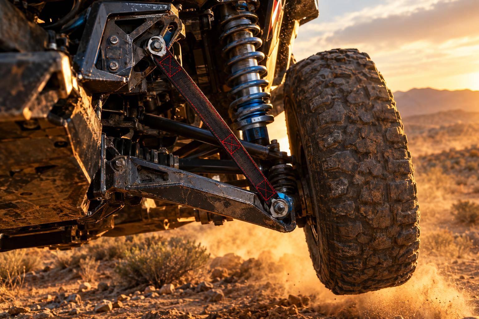
I set limit straps to stop droop before shocks top out, joints bind, or hoses pull tight – not by ride height alone. That starts with strong mounts, a straight pull when the strap engages, and length that accounts for the maker’s stretch allowance.
My fitment check comes down to 3 things:
- Mounts: Check structural support, tab spacing, eyelet movement, and bolt access.
- Travel: Safely cycle compression, droop, steering, and articulation. Keep the strap slack at ride height and clear of moving parts.
- Final checks: Follow torque and welding instructions, then recheck engagement and inspect for wear after the first drive.
There’s no single correct strap angle. <u>The loaded pull path and safe droop limit decide the fit</u> – with manufacturer guidance setting the details.
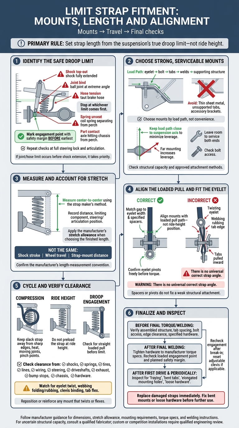
Limit Strap Fitment: Mounts, Length and Alignment
Choosing Upper and Lower Mount Points
Mount Locations and Structural Support
After confirming full droop, choose mount points that keep the load path short and strong.
Choose mounts by load path, not convenience. Follow the strap’s pull through the eyelet, bolt, tabs, welds, and supporting structure. Avoid thin sheet metal, unsupported tabs, and accessory brackets that weren’t designed for suspension loads.
| Location | Advantage | Limitation | Reinforcement check |
|---|---|---|---|
| Frame or crossmember | Fixed upper attachment | Clearance and local loading vary | Verify structural capacity and bracket support |
| Axle housing | Moves with a solid axle | Welding and articulation require care | Verify attachment method and housing suitability |
| Control arm or radius arm | Follows suspension movement | Mount position changes leverage | Confirm arm capacity and approved attachment method |
| Shock-mount structure | May provide a direct load path | Existing capacity may not accommodate strap loads | Verify capacity for added and combined loads |
Before welding to an axle housing or arm, check material thickness, the approved attachment method, seal clearance, and capacity to handle bending and twisting. Protect heat-sensitive parts. If you’re unsure about capacity, have a qualified fabricator assess the structure.
Keep the strap’s load path close to the suspension axis when the design allows. Mount points farther from that axis put more leverage on the structure.
Once you’ve checked the structure, make sure the mount clears every moving part through full travel. Strength comes first, but clearance and service access determine whether the location works in practice.
Clearance and Bolt Access
After choosing a strong mount, make sure you can install, remove, and inspect the hardware without taking apart unrelated parts.
Check clearance around shocks, springs, tires, lines, wiring, steering, driveshafts, exhaust, bump stops, and the chassis. Include the proposed brackets, eyelets, and hardware – not just the strap. On a solid axle, cycle one-wheel-up and one-wheel-down articulation to check the load path and bracket clearance.
Leave room to service both ends. Make sure the bolts can slide out and a wrench can reach the hardware. At compression, check that the slack strap can’t hang into sharp edges, heat, moving joints, or pinch points.
sbb-itb-afc4690
Setting Strap Length and Droop Engagement
With the mount points fixed, use the suspension’s actual droop limit to set strap length.
Finding the Safe Droop Limit
Set strap length from the suspension’s true droop limit – not ride height. Cycle the suspension slowly. Stop at whichever limit comes first: shock top-out, joint bind, hose tension, spring unseat, or part contact.
Repeat the check at full steering lock and in the relevant articulation positions. Mark where the strap should engage, leaving a planned safety margin before the limit. If the shock sets the limit, leave a small margin before full extension. Any joint or hose limit that occurs sooner takes priority. Shock stroke, wheel travel, and strap-mount distance are not the same measurement.
At the marked position, measure center-to-center between the mounting holes using the strap maker’s method. For each side, record the distance, the limiting component, and the steering or articulation position. Don’t rely only on the shock’s published extended length.
Use this measurement as your starting point, not the finished strap length.
Allowing for Stretch and Break-In
Apply the manufacturer’s stretch allowance when choosing the finished length. Before ordering, confirm how the manufacturer measures strap length and account for its specified stretch allowance.
Keep the strap slack and unloaded at normal ride height. After installation, cycle the suspension again to check that the strap engages before the identified limit without restricting normal compression. Recheck after the first drive and adjust according to the manufacturer’s instructions. Do not preload the strap at ride height.
The measurement only works if the strap pulls straight. Next, check the angle, tab spacing, and side load.
Strap Angle, Tab Spacing, and Side Loads
Once the length is set, check how the mounts carry load as the suspension moves.
Mount Layout and Alignment
Align the mounts with the loaded pull path – not their ride-height position. At full strap load, the eyelets should seat without twisting, and the tabs should carry the pull in their reinforced direction. A pull across a tab can bend it and load one edge of the webbing. Use double-shear support where space allows, but don’t expect spacers or pivots to fix a weak structural attachment.
| Mount layout | Alignment | Side-load risk | Fabrication needs | Inspection focus |
|---|---|---|---|---|
| Direct aligned mount | Straight pull when the strap engages | Lower if movement stays within available articulation | Supported tabs placed along the loaded pull path | Eyelet seating and angle changes |
| Angled fixed tab | Depends on tab orientation and suspension movement | Higher when the pull moves beyond the allowed range | Precise placement and support | Twist, abrasion, and tab bending |
| Suitable pivoting clevis | Follows angular movement within its range | Reduced only within its supported articulation range | Rated hardware and enough clearance | Free movement, wear, and binding |
Tab Spacing and Eyelet Fit
Use double-shear tabs where practical, with the eyelet centered between them. Match the gap to the eyelet width and manufacturer-specified spacers. The bolt should pass squarely through without drawing the tabs inward. Check that the tab thickness, bolt diameter, and sleeve length fit the assembly. Torque only after confirming that the eyelet pivots freely; clamping it can cause failure.
With the hardware fitted, check how the mount layout affects travel control.
How Strap Geometry Affects Travel Control
There is no universal correct strap angle. Strap extension follows movement between the mounts, not wheel travel alone. Moving the lower mount changes leverage, so the same strap can limit different amounts of travel. Strap stretch can also allow different amounts of added wheel travel.
Cycle the suspension to check the layout rather than relying on a simple angle formula. Get a qualified engineering review for custom or competition installs.
Checking Alignment Throughout Travel
Mock up the mounts before final welding, then check them through the suspension’s full range of motion. Include full droop, ride height, compression, steering lock, and any applicable one-wheel-up or cross-axle articulation.
Watch for eyelet twist, webbing that folds or rubs a tab edge, clevis binding, and tab flex. Keep the strap clear of tires, lines, joints, shocks, arms, and frame members. Reposition or reinforce any mount that twists or flexes. Don’t hide the problem with spacers.
Final Fitment Checks
Hardware and Geometry Checklist
After checking geometry, lock the hardware and confirm final fit. Before final torque or welding, check the assembled structure, tab spacing, bolt access, and edge clearance. Make sure all specified bolts, washers, spacers, and tabs are in place and secure.
After final welding, tighten the hardware to the manufacturer’s torque specs. Then recheck the same loaded engagement point to confirm it still leaves the planned safety margin. If the kit has an adjustable clevis, reset engagement after break-in.
Post-Drive Inspection and Product Guidance
After the first drive, check for fraying, bent tabs, elongated mounting holes, and loose hardware. Repeat these inspections periodically. Replace damaged straps immediately, and fix bent mounts or loose hardware before further use.
For LSK Suspension kits, verify dimensions, stretch allowance, mounting requirements, torque specs, and weld-on instructions.
FAQs
How do I know my strap mounts are strong enough?
Your strap mounts need to withstand extreme forces as the suspension cycles and keep their geometry consistent under load. Use high-strength components built for harsh off-road use, such as the CNC-cut steel clevises in LSK Suspension kits.
Limit straps control travel and protect your shocks. If you don’t have advanced fabrication skills, work with a professional installer to make sure the mounts are properly integrated and can handle the stress.
How can I tell if tab spacing causes side loading?
Incorrect tab spacing can make the limit strap clevis bind or pull at an angle rather than sit flush. Check for uneven wear, rubbing, or deflection under load. Tabs spaced too far apart allow side-to-side movement. Tabs spaced too close together pinch the clevis and restrict articulation.
LSK Suspension’s machined clevis is designed for a 2.75-inch tab spread to provide the correct fit and prevent these alignment issues.
Do I need shorter straps after moving the mounts?
You’ll likely need to adjust your limit strap length, but shorter straps aren’t always the answer. Moving the mounts changes the distance between the upper and lower tabs.
Measure that distance at full droop. The straps should prevent suspension overextension and protect your shocks without limiting intended travel. An adjustable clevis kit from LSK Suspension can help you fine-tune the fit.
Leave a Reply