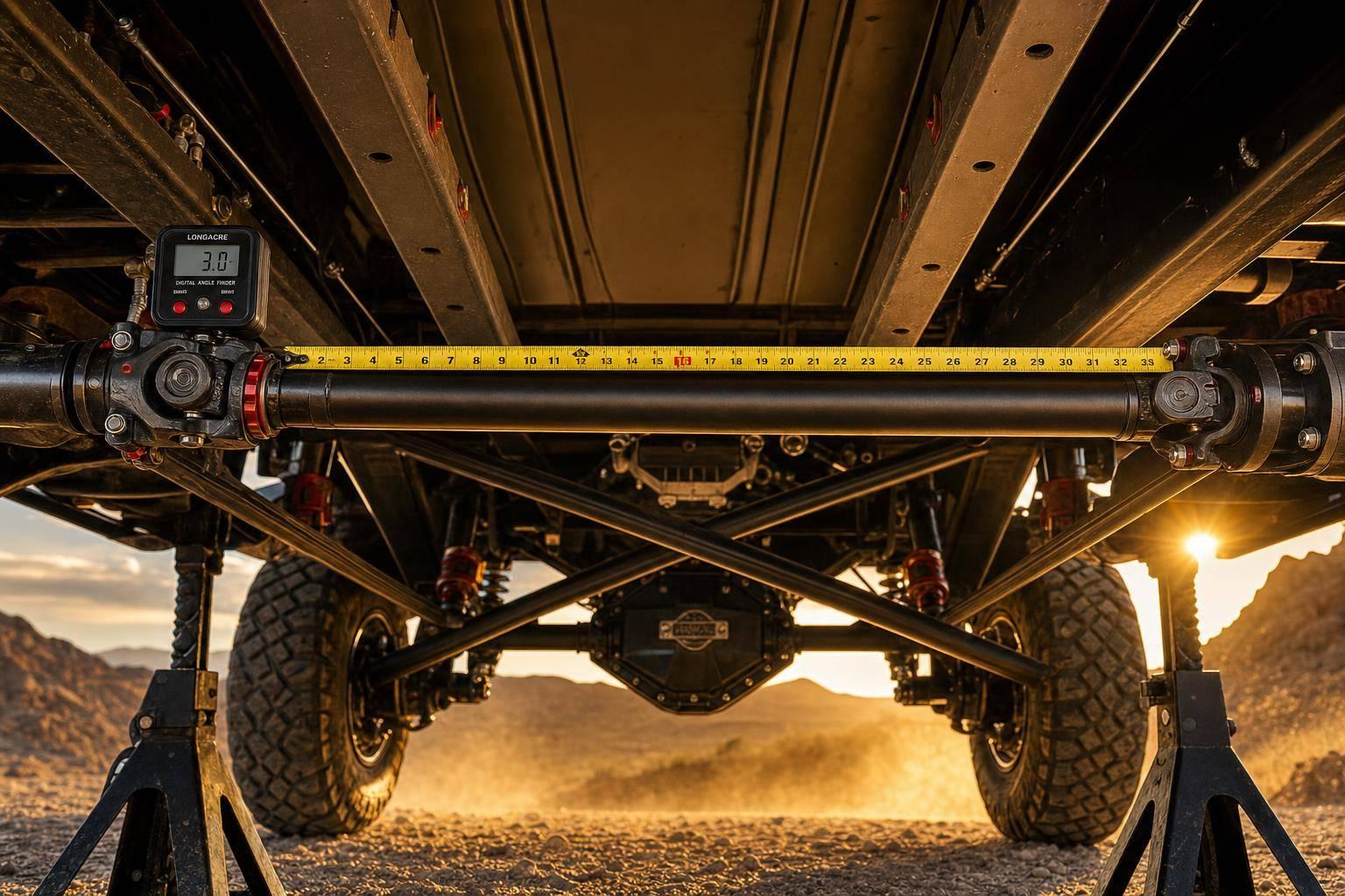
A custom off-road driveshaft fails fast when length, slip, and angle are wrong. If I were building one, I’d measure from ride height to full bump and full droop, size the tube and U-joints for tire load and shock load, and confirm the shaft still has room to move without binding or bottoming out.
Here’s the short version:
- I’d measure the shortest and longest distance between connection points before cutting.
- I’d check transmission, shaft, and pinion angles at ride height, full compression, and full droop.
- I’d match the build parts to use:
- Tube diameter and wall thickness for torque and impact load
- 1310, 1350, or 1410 joints based on tire size and abuse level
- Single U-joint or double Cardan/CV based on angle
- I’d verify yoke phasing, clearance, weld quality, and balancing before use.
- After install, I’d make sure the slip section still has at least 1 inch left at full compression and no bind at full droop.
- After trail runs, I’d inspect for rust dust at caps, dents, clunks, vibration, and spline wear.
A few numbers stand out:
- Long-travel kits can add about 13.5 to 18 inches of wheel travel.
- Some setups move the wheelbase 1.25 inches forward.
- A rear setup can see only 1/2 inch of plunge over 17 inches of wheel travel.
- Grease slip splines about every 10,000 miles for street use, and after every mud or water crossing for hard off-road use.
If I had to boil the whole job down, it would be this: measure first, build for full suspension travel, and inspect early before a small issue turns into a trail failure.
How to Build a Custom Driveshaft – Rock Rods Tech
sbb-itb-afc4690
Measure Length, Slip Travel, and Operating Angles Before You Cut Anything
Start at ride height, then move the suspension from the bump stop all the way to full droop. Write down the shortest and longest yoke or flange distance. Those two numbers tell you how much slip travel the shaft needs.
Cutting first and measuring later is how small problems turn into a headache. A driveshaft has to deal with movement through the whole suspension range, not just when the vehicle is sitting still in the shop.
How to Measure Common Driveshaft Length Configurations
Use the same reference points every time. If you switch methods halfway through, your numbers can drift fast.
Common reference points include:
- Flange face-to-face
- Yoke centerline-to-centerline
- Seat-to-seat
Pick the method that matches your hardware and stick with it from start to finish.
How to Check Transmission, Shaft, and Pinion Angles
Use a digital angle finder to measure the:
- Transmission output
- Driveshaft tube
- Pinion flange
Take those readings at ride height, full compression, and full droop. Each U-joint angle is the difference between the driveshaft and the part connected to it.
These measurements help you set slip length, joint layout, and pinion angle before you cut the shaft. And that matters, because those angles decide whether a single U-joint setup works or if a double Cardan layout makes more sense.
Choose Tube Size, U-Joints, and Joint Layout for Your Terrain
Match the tube, joints, and layout to torque, suspension travel, and speed. Start with the tube’s strength, then pick joints that fit the angle range.
Tube Diameter and Wall Thickness: Strength vs. Weight
Pick tube diameter and wall thickness based on torque and shock load. For high-stress builds, 4130 chromoly gives a strong strength-to-weight ratio. On heavier or high-speed builds, critical speed can matter just as much as torque. That’s why it’s smart to have a driveshaft specialist check wall thickness for your setup.
1310, 1350, and 1410 U-Joints and Matching Yokes
Joint series choice comes down to torque load and how hard the truck gets used. The 1310 series is common on stock and mildly built trucks. But once you step up to 37-inch to 39-inch tires and tougher use, 1350 or 1410 series joints are usually the better fit.
Yokes need to match the joint series exactly, so check cap size and yoke size before ordering parts. If those parts don’t line up, the rest of the setup won’t either. Joint size also sets the angle and load limit for the layout you choose next.
When to Use a Double Cardan or CV Layout
A single-cardan shaft works well when operating angles stay low and both ends of the shaft are close to equal. As angles go up, a double cardan, or CV-style front joint, handles steep angles more smoothly. Use the largest measured operating angle to choose the right layout.
This gets even more important on long-travel suspension. LSK Suspension long-travel kits typically provide 13.5 inches to 18 inches of usable wheel travel and move the wheelbase 1.25 inches forward, and both changes affect driveshaft geometry. If your build includes major suspension changes, sort out the operating angles before locking in a joint layout. What works at stock ride height usually doesn’t work the same way after a long-travel kit goes in.
Build, Weld, Install, and Verify the Shaft
Once the dimensions and angles are locked in, the job shifts from planning to execution. And this is where a lot can go wrong. A small fit-up mistake or a poor weld can turn an otherwise good shaft into a vibration headache on the trail.
Cutting, Fit-Up, and Yoke Phasing
Before cutting the tube, cycle the suspension through its full range of motion. This lets you confirm slip travel and check clearance to the crossmember, exhaust, and chassis. It’s a simple step, but it can save you from cutting a tube that looks right on paper and still causes trouble once the suspension moves.
Yoke phasing also needs to stay correct. After you’ve locked in the final length, cut the tube to size and mock up the shaft at ride height before final welding. That mock-up gives you one last chance to catch alignment or clearance issues before the shaft is finished.
Welding and Balancing Without Creating Runout
Final welding should be handled by an experienced fabricator. The goal is to avoid warp, runout, and the kind of vibration that can sneak in from a shaft that’s only slightly out of line. Even when the build looks good, most custom shafts still need professional static and dynamic balancing.
Final Installation Checks at Full Compression and Droop
After installation, cycle the suspension again through full compression and full droop. At full compression, make sure the slip yoke still has at least 1 inch of travel left so it can’t bottom out into the transfer case. At full droop, rotate the shaft by hand and check for bind or rough spots.
Clearance matters through the entire arc of travel, not just at ride height. Check the shaft against the crossmember and exhaust at every point.
Plunge, or slip-yoke in-and-out travel, is a big part of this. In some setups, the numbers can be surprisingly small. A well-designed long-travel rear suspension can see as little as 1/2 inch of driveshaft plunge over 17 inches of wheel travel.
"One cool thing about dropping the front leaf pivot down a couple of inches is it helped with driveshaft plunge. 1/2" of plunge for 17" of rear wheel travel." – Van Syverud, Co-owner, LSK Suspension
If your build changes wheelbase, ride height, or suspension pivots, cycle the driveshaft again and recheck the geometry for new interference or plunge issues. Then, after the first trail run, inspect the shaft one more time for marks, looseness, or vibration.
Inspect, Maintain, and Correct Problems Early
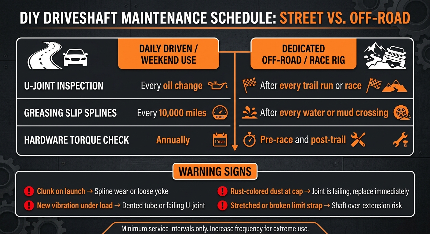
DIY Driveshaft Maintenance Schedule: Street vs. Off-Road
What to Inspect After Trail Use or Race Prep
Once the shaft passes full-travel checks, maintenance is your next layer of protection. A quick inspection after trail use can spot trouble before it leaves you stuck on the trail.
Start with the U-joint caps. Look for rust-colored dust. That usually means the needle bearings inside are coming apart. Then check the tube for dents or scrapes from rock hits. After that, inspect the slip yoke for bottoming marks, binding, or any new wear.
If your rig has a long-travel setup or sees race use, inspect the shaft after every trail run or race event. Don’t wait for a mileage interval. Check your limit straps too. If a strap is stretched or broken, the suspension can over-extend past what the shaft was built to handle.
Greasing Intervals and Common Failure Symptoms
For greaseable U-joints and slip splines, service intervals depend a lot on how the rig is used. A daily driver can usually go about 10,000 miles between spline greasing. But if the rig sees mud or water, service it after every crossing. Sand and grit wear out seals fast, and they chew through bearings and splines.
Use this schedule as the minimum service interval:
| Component | Daily Driven / Weekend Use | Dedicated Off-Road / Race Rig |
|---|---|---|
| U-Joint Inspection | Every oil change | After every trail run or race |
| Greasing slip splines | Every 10,000 miles | After every water or mud crossing |
| Hardware Torque Check | Annually | Pre-race and post-trail |
A few failure signs are worth memorizing because they tend to show up before a part lets go:
- A clunk on launch usually means too much spline wear or a loose yoke.
- New vibration under load usually points to a dented tube or a failing U-joint.
- Rust-colored dust at a cap means the joint is already done. Replace it now.
Replace worn parts as soon as you see these signs.
Conclusion: Core Rules for a Reliable DIY Driveshaft
Keep slip travel adequate, keep angles in spec, and inspect the shaft after hard use.
FAQs
How do I know if my driveshaft needs more slip travel?
Your driveshaft needs more slip travel when suspension movement causes major axle plunge. As the distance between the transmission and differential changes through the suspension cycle, the driveshaft has to extend and compress with it.
If it can’t keep up with that movement, you can end up with binding or part damage. Checking the amount of plunge – such as 0.5 inches in some long-travel setups – helps you see whether your current slip yoke or driveshaft design can handle the job.
When should I use a double Cardan driveshaft?
Use a double Cardan driveshaft when your setup creates steep driveshaft angles that can cause vibration or binding with a standard U-joint setup.
This comes up a lot in custom off-road builds, especially when suspension geometry has been changed. A double Cardan helps keep power delivery smoother because it splits the operating angle between two joints instead of forcing one U-joint to do all the work.
The result is more even driveline performance, which matters when the suspension is cycling and the shaft angle gets steep.
What size U-joint is right for my build?
The right U-joint size comes down to three things: your vehicle setup, horsepower, and how you plan to use it. If you’re building a custom driveshaft, talk with a professional fabricator or driveline specialist. They can help make sure the shaft is built to handle your drivetrain’s torque and operating angles.
It’s also worth knowing that changes to suspension pivot points can alter driveline plunge and geometry. That can affect how the whole setup moves under load and through suspension travel. A professional can help sort out those tradeoffs so you get the suspension movement you want without giving up dependable U-joint performance.
Leave a Reply